Raspberry Pi Sunfounder Gpio Layout
I have recently bought a Raspberry Pi together with a SunFounder LCD Starter Kit in order to do some experiments. Of special interest are the GPIO pins that enable communication with electroinc components like LEDs, buttons, all kinds of sensors and even simple LED screens.
These pins can be addressed from a python program using a simple syntax. An example is provided here:
import RPi.GPIO as GPIO  ## Import GPIO library
GPIO.setmode(GPIO.BOARD) ## Use board pin numbering
GPIO.setup(7, GPIO.OUT)  ## Setup GPIO Pin 7 to OUT
GPIO.output(7,True)      ## Turn on GPIO pin 7
This will turn on GPIO pin no. 7. But which one is it? It turns out this question is surprisingly hard to anwser. There are several subtilities in the pin referencing:
- There are two different referencing schemes:
BCMandBOARD - The BCM reference schemes differes for different Raspberry Pi versions
- The SunFounder extension board (see below) mixes up the
pins again and is neither consistent with
BCMnor withBOARDreferencing.
As you might imagine, this is more than enough complexity to cause a lot of errors. In this note I am going to explain how to get a thorough grip on the referencing scheme.
Setup a LED Probe
Grab a 3.3V LED, a 1K OHM resistor and some wires and connect them like described in this document here. The top right pin of the Raspberry Pi board is always connected to 3.3V. The lower right pin is always connected to the ground. The connected LED is shown below:
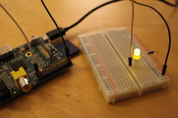
Once you have completed this setup, you can disconnect the wire from the ground pin (white wire) and use the free wire as a probe.
Now we want to identify pin “No 7” in the above example. By probing along the with our white wire we find several pins that are also connected to a ground (LED on) or a potential of 3.3V or 5V (LED off). But which on is the right one?
To simplify this task, we can set pin “No 7” to an alternating signal. The following script does the trick:
sudo python blink.py BOARD 7
Now we can find the correct pin by watching out for a blinking LED. (Solution: 4th pin counting from the black wire downwards.)
In a similar fashing we can go on and find all pin references in the
BOARD and BCM schemes. The full table for my RPi looks
like that:
| BCM | BOARD | BOARD | BCM |
|---|---|---|---|
| 3.3V | (1) | 2 | 5V |
| 2 | 3 | 4 | 5V |
| 3 | 5 | (6) | GND |
| 4 | 7 | 8 | 14 |
| GND | (9) | 10 | 15 |
| 17 | 11 | 12 | 18 |
| 27 | 13 | (14) | GND |
| 22 | 15 | 16 | 23 |
| 3.3V | (17) | 18 | 24 |
| 10 | 19 | (20) | GND |
| 9 | 21 | 22 | 25 |
| 11 | 23 | 24 | 8 |
| GND | (25) | 26 | 7 |
The numbers in parantheses correspond to pins, that are not available via the GPIO api but have a special meaning. E.g. the pins 1 and 25 used in the above examples are always wired to 3.3V and ground (GND).
Meltwaters GPIO Layout Script
Thankfully, you do not have to repeat this exercise above for your every
RPi again. Meltwaters has published a script that finds the precise Raspberry Pi version and
prints out the BCM pin layount on the console.
The script can be used as follows:
curl http://pastebin.com/raw.php?i=T43HpgYp > iolayout.py
less iolayout.py
Check carefully, that you downloaded the right code. Then run as root:
sudo python iolayout.py
You should see an output that resembles the above tables but might differ slightly.
Monks Raspberry Pi leaf
If you want to make sure you do remember the BCM labeling of the pins,
you can us the following brilliant “Raspberry PI leaf” by Dr. Monk:
It can be obtained
here
make sure to downlaod the right one by comparing with the output of iolayout.py.
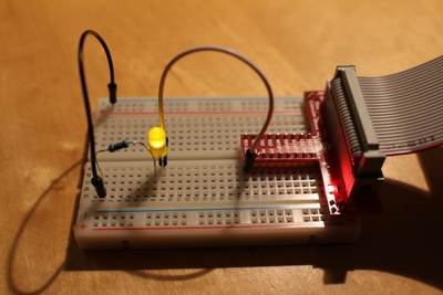
SunFounder Extension Board Referencing
The SunFounder starter kit comes with an ribbon-cable and an extension board that grately simplifys access to the pins.
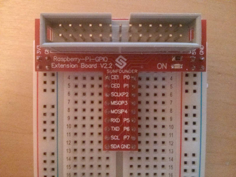
Surprisingly the lables on the SunFounder extension board do not match the BCM, nor the BOARD referencing scheme. Manuall checking with the LED Probe reveals the following table:
| BCM | BOARD | EXT. | EXT. | BOARD | BCM |
|---|---|---|---|---|---|
| 7 | 26 | CE1 | P0 | 11 | 17 |
| 8 | 24 | CE0 | P1 | 12 | 18 |
| 11 | 23 | SCLK | P2 | 13 | 27 |
| 9 | 21 | MSOP | P3 | 15 | 22 |
| 10 | 19 | MOSP | P4 | 16 | 23 |
| 15 | 10 | RXD | P5 | 18 | 24 |
| 14 | 8 | TXD | P6 | 22 | 25 |
| 3 | 5 | SCL | P7 | 7 | 4 |
| 2 | 3 | SDA | GND | - | - |
The wiring of the LED probe on the extension board is much easier to handle, and with the above table the pin referencing can easily be translated to the SunFounder extension board labels.